Roller copier for milling cutter. Types and features of copy milling machines. Pay attention to the support for parts when performing work
Copying equipment is used in cases when it is necessary to manufacture parts according to a specific template within a small batch. In some cases, a copy-milling machine is used under conditions of large-scale production, like the CNC version. This is due to the fact that the machine in question is capable of creating products, the shape of which is most consistent with the original sample, like CNC machines, the movement of the cutter is set automatically. The main feature that a copy milling machine possesses is a high processing speed.
The purpose
Often, a copy-milling machine is used to perform volumetric and plane processing, its operation is similar to the options on which the CNC system is installed. At the same time, special models allow wood processing by volume, when a volumetric model is used as a copier. In the field of woodworking, processing by volume allows:
- create ornaments and various inscriptions.
- engrave shaped profiles.
- create complex patterns with faces or planes located in different planes.
The wood machine in question is often used in the production of furniture. Many decorative parts that have a complex shape are created using a similar machine.
Principle of operation
The possibility of significantly accelerating the production process of complex products is due to the peculiarities of the work that the copy-milling machine possesses. As with metalworking, woodworking uses a cutting tool called a milling cutter.
The main points of work can be called:
- The cutter carries out the creation of a contour or surface, which are specified using a copier.
- The link between the cutting tool and the tracking device is a mechanical, hydraulic, pneumatic system. The woodworking machine most often has a mechanical feed and control system.
- A flat template, a previously created reference model, a spatial model, a photocell, a contour drawing can serve as a copier. In some cases, these machines are equipped with CNC, which makes them versatile.
- Samples serving as templates can be made of metal, wood, plastic, or other material.
The copy-milling machine works as follows: a sample of a different type is installed, a tracking device is brought to it, which, through a certain type of connection, transfer the required force to the cutting tool.
Classification
- pantograph on wood for a router. this option can work in 2 or 3 dimensions;
- a universal type, also referred to as a pantograph with a pivoting arm. as a rule, the sleeve is located in a vertical plane;
- there are versions that have several spindles to speed up the machining process;
- with mechanical, electrical, hydraulic feed;
- photocopied view of contour transfer for guiding the cutting tool.
There are many schemes according to which you can create a copy-milling machine with your own hands. A typical version usually consists of the following elements:
- Desktop;
- bearing frame;
- milling head.
To carry out the procedure for changing the cutting mode, the height of the table is changed, the head with the cutter has an electric drive, which sets the cutting tool in motion, and often a gear mechanism is included in the system to change the speeds.
The pantograph itself can be made as follows:
- Made of wood. You can create such a pantograph with your own hands, but at the same time it will have low processing accuracy, since the connection of the wooden parts occurs with the help of a loop. Fastening with hinges is characterized by backlash.
- Drafting pantograph made of metal - allows you to create copies at various scales, but cannot be used to create volumetric copies.
When creating a machine with your own hands, you should take into account that many parts may have flaws and inconsistencies in size. This situation associated with vibration and shaking of the base, which is difficult to avoid. When changing the direction of movement of the cutter, errors are also possible. Due to the internal stress of the wood workpiece, the workpiece can be bent. Therefore, it is recommended to create such equipment only for narrow-profile production, when the machine will be designed to create one part. It is almost impossible to avoid the problems under consideration, however, provided that the same part is processed, a gradual improvement in the design is possible.
Milling is a type of mechanical processing of materials using a special cutting tool - a milling cutter. The method allows you to obtain a high quality of accuracy and the degree of roughness of the processed surface. In addition, it is distinguished by significant performance.
Surface treatment is carried out by the method of counter milling, when the rotation of the cutting tool is opposite to the direction of feed, and by passing milling - a method in which the direction of rotation of the cutter and feed are identical. By using milling cutters with cutting edges made from modern ultra-hard materials, it is possible to replace the grinding operation.
Milling equipment is divided into universal and specialized. In the first case, these are general-purpose machines for performing longitudinal and continuous milling, with a tool mounted on a console and not. In the second, there is a mechanism for cutting threads, splines, making gears and keyways, and milling using a copier.
In production, there is often a need to manufacture several pieces, a batch, or even a series of identical parts. For this, milling equipment equipped with a pantograph is used.
In the household, the functions of a milling machine are usually performed by a hand-held milling cutter. To carry out the maximum list of works, the router is equipped with a whole set of accessories. The main equipment is supplied with the equipment, additional equipment is purchased or manufactured independently. These are a variety of stops, clamps, templates. But you can go even further and make a copier for milling volumetric parts.
Milling and copying equipment: principle of operation
The principle of operation of such a device is to accurately transfer the movements of the copying head through the profile-holder to the cutting tool.
It is rather difficult to acquire a copy milling machine, therefore craftsmen make it with their own hands from scrap materials. Everything happens by trial and error. Therefore, the masters advise you to first assemble the duplikarver, and only then introduce it into mass production. Typically, this stage is preceded by more than one major fit and rework.
Milling and copying equipment: applications
On milling copying machines, you can process not only flat, but also three-dimensional parts. With their help, along with simple milling operations, you can perform engraving, repeat patterns, patterns and inscriptions. The design of the machine is quite simple, and any craftsman can make it.
Copy milling machines allow processing not only wooden parts, but also cast iron, steel and plastic blanks, as well as non-ferrous metal products. This is ensured by quality tools made from high speed steel and carbide alloys. The copying machine allows you to mill not only straight, but also curved surfaces. In this case, the details are completely identical.
Milling and copying equipment: design
The typical design of a copy milling machine is quite simple. It consists of a work table and a system of guides with clips for attaching the router and copier.
It is quite difficult to make a universal copy-milling machine at home, and even this is not very necessary. For home conditions, equipment with a narrow specialization is usually created.

Making a copy-milling machine: materials
To create a duplikarver at home with your own hands, you should draw an elementary sketch, which will become a guide to further actions. In addition, you need to stock up on some materials. This:
- Knee case-hardened polished shaft Ø 16 mm.
- Linear bearings in the amount of 2 pcs.
- Rail guides 900 mm long - 2 pcs. For the convenience of fastening, their length is taken as a multiple of 150.
- Split linear bearings, 4 pcs. It is desirable to use bearings with a clamping screw to adjust the tightness of the fit on the rail.
- Profile tube 30 × 60 with a wall thickness of up to 3 mm.
- Metal plate 900 mm long and 100 mm wide.
- End posts in the amount of 2 pcs.
- Movable element in the form of a plate - 1 pc.
- Rocker arm for copier and router attachment - 2 pcs. The length is chosen arbitrarily.
- Movable couplings - 2 pcs.
- Profile pipe 40 × 40 with wall thickness up to 3 mm.
- Crown coupling for turning part and template.
Making a copy-milling machine: tool
After that, you need to prepare a tool that will definitely come in handy for assembling the structure of the machine. This:
- angle grinder;
- cutting and cleaning disc;
- welding machine;
- welding mask;
- petal disc or brush;
- self-tapping screws for fastening rail guides and moving elements;
- electric drill;
- screwdriver;
- measuring instruments: tape measure, vernier caliper;
- center punch and scribe.
Making a copy-milling machine: step-by-step instructions
After everything is ready, the direct assembly of the copy milling machine begins.
Step # 1
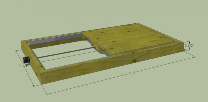
It is necessary to cut two pieces of length 950 mm from the profile pipe 30 × 60 for fastening the rail guides. A stock of 50 mm is needed to install limit switches in order to prevent the linear bearings from jumping off.
Step # 2
The 40 × 40 profile pipe must be cut into blanks for the base. Based on the existing sketch, you need to cut off two pieces of 1350 mm and two pieces of 900 mm.
Step # 3
From the same pipe it is necessary to cut off small racks. Their linear size depends on the height of the subsequently processed parts.
Step # 4
Now you need to remove rust from the pipes. To do this, you can use a flap disc or a brush.
Important! Before using the brush, pay attention to the maximum number of working revolutions on it and on the grinder. The value of the speed of rotation on the brush must exceed the number of revolutions of the equipment.
Step # 5
After that, we weld all the joints and clean the seams with a 6 mm thick grinding wheel.
Step 6
Then it is necessary to achieve parallelism of the rails. To do this, you need to make the connection between the rack and the base of the rail detachable. It is necessary to take a washer according to the internal dimension of the rack, weld a nut to it and screw in a bolt. The bolt at this stage is needed in order to install the nut with the washer in the cavity of the pipe-rack flush and in a strictly vertical position, and not damage the thread during welding. This must be done with all four racks.
Step 7
Weld the racks to the base.
Step 8
At the base of the rail at the junction with the posts, you need to drill holes: in the upper shelf for the bolt head, in the lower one - for the thread.
Step 9
Install the rail guides on the base (pipe 30 × 60), pre-drilling the holes, and fix with self-tapping screws for metal.
Step 10
Mount the rails and bases and tighten with bolts.
Step 11
Check the parallelism of the guides. If it is absent, it is necessary to make adjustments by placing foil of different thickness on the posts under the guide.
Step 12
On a metal plate, you need to mark and drill holes for attaching split linear bearings and end posts.
Step 13
After that, you need to make a movable element by welding to a metal plate of a rocker arm 300 mm long for a stylus and a router, then attach linear bearings to it.
Step 14
After that, the movable element must be put on a polished shaft, along the edges of which end posts are installed.
Step 15
The entire structure must be installed on a metal plate 100 mm wide and secured with end posts with self-tapping screws.
Step 16
Then, split linear bearings must be installed on the metal plate from the bottom side.
Step 17
After that, the hinged structure is put on the rail guides with split bearings and the limit switches are installed.
Step 18
At the end of the rocker arms, movable couplings are installed and a probe and a milling cutter are attached.
Step 19
In order for the workpiece and the part to rotate synchronously, it is necessary to connect them with couplings. An asterisk and a crown are suitable for control. The copy milling machine is ready. The design has 5 degrees of freedom. Movement along the X axis is provided by the movement of the structure along the rail guides, movement along the Y axis is provided by the movement of the movable element along the polished shaft, movement along the Z axis is provided by the movement of the rocker arms.
Additionally, due to the movable couplings, the probe and the milling cutter can move left and right along the axis of the rocker arm, and there is the possibility of synchronous movement of the template and the workpiece. This makes it possible to process parts of almost any shape.
Copy milling machines for metal in mass and serial production
Copy milling machines for metal are used in mass production. With their help, propellers for ships, turbines of engines with reactive thrust, pump impellers, dies for press-forging production, blanks for mechanical and foundry production are manufactured. In everyday life, copying equipment for metal is practically not used.
Pantograph for a router: design features
For scaling copying processes, there is a special device called a pantograph. It facilitates the processes of manufacturing parts with curved surfaces, allows you to make ornaments and patterns of any complexity in a reduced form. The cost of such a device is quite high. But making a pantograph at home with your own hands is quite realistic.
Pantograph for a router: principle of operation
The schematic diagram of the pantograph looks pretty simple. It is a square divided in half. All connections are hinged, so all sides are movable, and the square, when exposed, easily turns into a rhombus. The zero point located in one of the corners of the square is fixed rigidly. Relatively, its design can be modified, turning into a rhombus. A cutting tool is placed in the middle of the square. In the opposite corner of the square, a copier is fixed diagonally. The distance from the zero point to the cutter is a certain value A, and to the copier 2A. This gives a 2: 1 scale. The linear dimensions of the long and short sides of the pantograph should also differ from each other by 2 times.
Milling pantograph: materials
In order to make a pantograph with your own hands, you will need the following materials:
- Square metal profile 12 × 12
- Bearing 180201.
- Bushings for the outer bearing race.
- Pins according to the inner dimension of the bearing and M12 thread.
- Nut М12.
- Bolts М6 × 45
- M6 nuts.
- Bushing for copier fixing.
- Profile tube 40 × 40
- Hinge of a metal-plastic window.
- Dye.
- Masking tape.
- Metal plate.
- Screw for fixing the copier.
Milling pantograph: tool
In addition to the materials listed, you need a tool:
- Manual frezer.
- Angle grinder.
- Welding machine.
- Spanners.
- Measuring tool.
Pantograph for a router: step-by-step instructions for making your own hands
We proceed to the direct manufacture of the pantograph.
Stage 1. Cutting workpieces
It is necessary to mark and cut off the square profile according to the calculated dimensions. For convenience, you can use masking tape and a metal plate. Scotch tape will enable clear marking, and the plate will help to make an even and high-quality cut. The blanks for the platform for the milling cutter must be cut at right angles, and bevel should be made on the sections of the profile for the connecting rods for maximum fit of the bearing sleeve.
Stage 2. Drilling technological holes
All workpieces must be chamfered and drilled with Ø 6.2 mm holes for their further connection into the structure.
Stage 3. Welding of a platform for a milling cutter
After that, you need to weld a platform for a router.
Stage 4. Manufacturing of connecting rods
On the board, it is necessary to make a semblance of a conductor and rigidly fix all the parts to be welded. To do this, a hole is drilled in the board, and the bearing in the sleeve is clamped with a bolt, the square profiles of the connecting rods are fastened with clamps. Previously, two washers must be inserted between them and bolted together. After that, all joints of the structure are scalded and cleaned. Then you need to cut the bearing bush between the square profiles on each connecting rod. M6 bolts, washers and bearings must be removed. A mount for a router must be welded onto the frame, and an extension for scaling onto a short connecting rod at a point opposite to zero. The connecting rods can be painted for aesthetics.
Stage 5. Making a unit for attaching a copier
Now you need to grind two bushings with an inner diameter similar to the size of the copier. Drill a hole from the side and cut the threads to install the screw that secures the copier. After that, you need to cut off two pieces of a 12 × 12 square with a length of 20–30 mm and weld them on the side between the bushings. The size between the squares should be 12 mm.
Stage 6. Manufacturing of a bearing lifting mechanism
It is necessary to make a bearing lift assembly. To do this, the zero point finger must be welded onto a 12 × 12 profile piece and fixed to a 40 × 40 profile pipe using a loop from a metal-plastic window. The profile tube will serve as a place for attaching the pantograph to the table with a clamp.
Stage 7. Assembling the pantograph
The bearings must be installed in bushings and securely fastened by pulling the square profiles of the connecting rods with M6 bolts. Using your fingers, you need to assemble the connecting rods into a single structure. Fix the pantograph on the table with a clamp and install the router. The device is now ready for use.
Cutting tool for milling work: copy cutters
Copy cutters - a tool on which, in addition to the cutting part, there is a bearing. Its size is equal to the diameter of the cutter's cutting edge. The bearing can be located both at the top and bottom of the cutter. This is how the instrument is classified. It should be noted that the marking indicates the position of the bearing in the normal placement of the cutter - with the shank up.
They serve to perform copying work according to a template. When using a cutter with an upper bearing, the template is located on top of the part, if with a lower bearing position, then on the bottom.
Working with a hand router involves the use of any cutters. It's safe. The only thing is that when using a cutting tool with an upper bearing, you should pay attention to the overhang of the cutter so as not to damage the workbench.
Milling on a woodworking machine involves the use of milling cutters with only the lowest bearing position. This is due to the fact that a cutter with an upper bearing position has an open rotating cutting part in the area of the workpiece. Rough movement can result in serious injury. Such cutters are used on machines only in special cases with the maximum observance of the safety rules.
Copy-milling machines are unique equipment, with the help of which the most complex work on the manufacture of identical parts is performed. But for work at home, you can make simple analogues of such equipment and devices that will help in everyday life or a small business.
In order to ensure the normal operation of the milling machine, it is necessary not only to correctly handle the device used, but also to correctly use in other words - devices for this tool to be able to form a workpiece in accordance with the requirements of the master (that is, cutting off the edges and other places of the material where it is necessary, and not where "it happened"). So, it is precisely to give the processed material a clear planned shape in the farm that "adaptations" are used for a hand mill.
The difficulty of making homemade gadgets
Often, manufacturers themselves replenish their products at the production stage, but, alas, not every company will be able to please consumers with a full set of all the necessary tools. And why do this, if at any time you can make a suitable tool with your own hands in a garage. This can be done even without a preliminary drawing: their design is so primitive that even a novice master can cope with such work. To make a parallel stop or any other detail, it is enough to have a drawing of this device and a minimum set of tools with you. But if you want to make a homemade table for a hand router, you definitely cannot do without a drawing. You need to calculate everything correctly, designate the size of the table, and then proceed to work.
How to work with a hand router?
Before performing wood milling work, you need to make sure of the following:
- Is the cutter secured in the collet?
- Whether the attachment installed on the workbench matches its power and rpm.
- Has the required milling depth been set (when working with submersible devices, this indicator is measured using a special immersion limiter).
- When working with, make sure that a guide ring or a bearing is installed that provides the desired trajectory of the device (while the thickness of the cutter should be no more than three millimeters).
Pay attention to the support for parts when performing work
When considering the question "how to work with a hand router" it should also be noted that the part you are machining must always have some kind of support. For example, before starting the engine, the edge of the sole or bearing is pressed against a guide piece or template. Only then does the master switch on the machine and start milling.
Below we will consider what accessories for a router are, and how they are special.
Parallel stop
The rip fence is one of the few devices that come with every router. Therefore, there is simply no need for their independent development and manufacture. With regard to functions, with the help of the mentioned element, it is possible to make a reliable stop for the material to be machined, thereby ensuring the straight movement of the cutter relative to the base surface. The latter can act as a straight edge of a part, a guide rail or a table.

With this attachment for a hand router, you can quickly perform edging and milling of various grooves, keeping the material practically in the "dead center" position.
Guide rail
This tool has similar functions to the previous one. Like the rip fence, the bar provides extremely smooth, straight-line movement of the device. Working with a manual wood router using a guide rail can significantly reduce the time spent on processing a particular part. In addition, using the specified equipment, you can install the mechanism at almost any angle relative to the edge of the table.

In some cases, the design of the tools under consideration provides for the presence of special elements that facilitate the performance of certain operations (for example, it can be the function of cutting holes at the same distance opposite each other).
Copy rings and templates

Hand router attachments, such as copying rings, are a circular, raised bead plate that can slide along the surface along the template, thereby providing an accurate cutter path. Often, this element is attached to the sole of the workbench. At the same time, there are several ways to install it:
- Screwing the ring into the threaded hole.
- Installation of special antennae of the device in the holes on the sole.
With a hand router attachment such as a template, you can also achieve more accurate and efficient work. The designated

the element directly on the workpiece itself, after which both parts of the device are pressed against the machine using clamps. Upon completion of the work, experts recommend checking the condition of the ring - see if it is firmly pressed against the edge of the template or not.
Another feature of the tool under consideration is the ability to process not the entire edge, but only its corners. At the same time, some accessories for a hand router allow you to make roundings of four different radii at once. Thus, the template machining process is an excellent way to cut grooves for a part.
Compasses
These homemade accessories for a hand router are designed to move the entire machine around a certain circle. The design of the specified tool includes a main part (a compass, consisting of one rod), attached at the end to the base of the router, and a secondary part - a screw with a pin inserted into the hole of the machine. The value and is set directly by the offset of the machine relative to the structure of the device. Before starting work, it is necessary to carefully fasten the tool to the base and make sure that the router is in good condition and functioning properly. It is worth noting that the most effective and easy to use is the compass that has not one, but two bars at once.

Most often, this instrument is made of transparent plexiglass. A small metric scale is additionally applied on its surface. It is worth noting that some models of compasses can have a circumference of up to 150 centimeters. With the help of such a device, you can easily make a round tabletop for several people.
However, let's get back to the principle of work. With the help of an angle lever with a precise scale, copying is carried out over the workpiece. This gives you the opportunity to center the ring directly below the cutter. The angle arm, which is complemented by a special support plate, also enables precise edge milling.
The entire structure of this fixture consists of a base plate, a set of probes and a chip guard.
Devices for copying identical devices and parts
This characteristic means a set of tools, consisting of an angle arm and special copying probes, which are needed to manufacture a batch of identical parts. Most often, such equipment is used in cases where there is a need to replicate small wooden devices. But before you start working with such a router, it is necessary to prepare in advance the scale of the angular lever (the scale is 1/10 mm).

Once the scale has been set, you are 100 percent sure that the thrust ring is correctly centered under the cutter, the location of which depends on the values set on the bevel arm. Also, this adjusting element can be equipped with a support plate and a special mechanism that protects the surface of the device from chips. The use of such parts will significantly speed up and protect the processing of the edges of the products.
A copy-milling machine is used to create copies of products made of wood or other material of a certain shape. Such machines are used in large and small industrial enterprises, as well as at home to create various parts. Next, we will describe the principle of operation of such a machine and give recommendations on how to make it yourself.
1
Milling equipment with a copying installation is used for machining various planes. With the help of a high-quality machine, you can reproduce copies of volumetric forms, engrave, make patterns, drawings. Its main feature is its simplicity of design, while a rather complex list of works can be performed on it.
Copy milling machine
Such equipment has a simple principle of operation. A special copying probe is connected to the work plane. Further, he mechanically creates contours from a template or part. A cutter for wood or metal is attached to the working plane, depending on the purpose of the machine, which repeats the movements of the copying probe. In addition to these parts, the standard machine is also equipped with a cutter clamping system or milling unit, an electric motor and a guide system. Usually equipment for simple jobs for wood or plastic consists of three main elements:
- work surface with supporting element and frame;
- milling cutter or milling unit with a clamping mechanism;
- copying installation (pantograph) and copying probe.
Depending on the type of copy-milling machine, it can work in two or three dimensions. To create a simple template in two dimensions, the standard version with a clamping profile is sufficient, but for the production and boring of three-dimensional holes, the machine must be equipped with a pneumatic clamping unit, a drill and drill or other drilling unit. Depending on the configuration and capabilities, it can work not only with wood, but also with plastic, cast iron and other non-ferrous metals. For this, the machine is equipped with powerful and durable cutters for various materials, and the copying equipment is being improved for certain shapes.
DIY machines are often used in the household to drill keyholes, make frames, or create grooves in wood or metal parts.
2
Today there is a large number of copy-milling equipment of various designs with certain operating features. Their cost, as a rule, is quite high, so many amateurs make such devices with their own hands. A home-made version, of course, will differ from industrial counterparts, however, subject to certain conditions, it will perfectly cope with its functions.

Self-made copy milling machine
The standard scheme of a home-made machine consists of a working surface, a supporting structure and a milling head, which is equipped with an electric motor with a drive to create the ability to operate the head at two speeds. Thus, in order to do the installation yourself, you will need a set of certain equipment and tools, namely:
- main frame made of wood or metal;
- wood plywood or panel, bars, boards and slats;
- fasteners in the form of bolts, nuts, screws or nails;
- milling unit;
- a set of keys, saws or a hacksaw for metal for working with parts;
- guide system and metal pipes;
- electric motor with drive or manual drive;
- drills and drilling machine (for more complex options).
Instead of a wooden or metal frame, you can use a ready-made milling machine as a base, but fixing a copy device to it is much more difficult than making a machine from scratch. In this case, you will have to almost completely redo the milling machine, and this will take more time and additional equipment.
3
The basis for making the machine with your own hands will be manual. Secure it to a thick plywood support (at least 12 mm thick). Several holes are also made in the support for fasteners and a router holder. Additionally, a frame should be built and several bars should be made, which are installed along the edges of the support, they will hold the device during operation.

Manufacturing of a milling unit
We use a metal pipe of medium diameter as a guide. We install a carriage with a router inserted into it on the pipe. We attach a bar to the carriage, which plays the role of a copying probe, after which it is necessary to fix the horizontal bar on which the main template is attached. A machine made according to this principle can be used to process and create copies from simple household items, for example, door handles, locks, furniture legs. The milling unit with a motor is inserted into the carriage and connected to the power supply. A template is fixed on the support, a copying probe moves along it.
The milling cutter operates from the mains, the carriage moves manually, so that the working head follows the movements of the probe. To create more complex models, it is necessary to connect additional working heads and install a belt drive. Now it is possible to connect a self-made installation to the software, but this will require a CNC and additional equipment and tools. Such a homemade machine will cope with its everyday functions quite well.
4
The practice of using home-made copy-milling machines of various types shows that the final part made on such equipment has certain inconsistencies with drawings and shapes and some manufacturing defects in the form of chips and distortions. These flaws are caused by constant vibration of the machine and movement of the working head. It is very difficult to get rid of them in a domestic environment.

DIY copy milling machine
To avoid such shortcomings in the operation of home-made equipment, we recommend manufacturing highly specialized machines, and not equipment of a universal type. That is, before starting work on the manufacture of the machine with your own hands, you need to decide for which specific details it is planned to use it. This way you can optimally select the weight and dimensions of the hand-assembled copy-milling machine. It is important to remember that the larger the size of the parts to be machined, the more powerful and heavier the work set must be.
For large parts, additional holders and a more massive support are needed, this will maximize the damping of vibrations that will occur during operation. In addition, it is better to use an electric drive instead of a manual drive and make sure that the guides have sufficient safety margin. Remember also that the smooth movement of the cutting equipment in different planes depends on the type of the working surface, and therefore the final result.
V modern world often the need arises to make a copy of something, or to reproduce and repeat something. For this purpose, many enterprises widely use copy-milling machines, which are designed to create products, the shape of which is most consistent with a given initial sample. They enable the production of parts large circulations, while ensuring a high speed of processing and manufacturing of each element.
Features of the milling procedure
Milling is one of the most common machining methods. With the help of milling, rough, finishing and semi-finishing processing of shaped and simple surfaces of workpieces made of steel, non-ferrous metal, cast iron and plastics is carried out. Milling is characterized by a high level of productivity, which allows the end result to obtain products of the correct geometric shape.
Milling can be carried out in two ways: the procedure of counter milling (against the feed), when the feed is opposite to the direction of rotation of the cutter, and milling along the path (in feed), when the directions of rotation of the cutter and feed coincide. Using cutters that are equipped with modern cutting materials (mineral ceramics, synthetic superhard), you can process materials that are hardened to high hardness, thereby replacing the grinding procedure.

Milling machines are intended for milling surfaces of levers, strips, bodies, covers and brackets of simple configuration, complex configuration of contours (such as templates, cams), surfaces of body parts. Milling machines are divided into two main categories: general purpose machines and specialized machines. The first group includes longitudinal milling, cantilever, cantilever and continuous milling machines. The second category includes thread milling, gear hobbing, slot milling, keyway milling and copy milling machines.
The purpose of the copy milling machine
It is customary to use copy-milling machines to perform copying work in volume and on a plane, as well as in volume using volumetric models and corresponding copiers, for engraving various shaped profiles, patterns, ornaments and inscriptions, as well as for light milling work. An indisputable plus of such units is that he is able to perform incredibly complex patterns with his own simple device.
On the machine, you can perform various milling work on steel, cast iron and non-ferrous metals using high-speed and carbide tools in large-scale and small-scale production. On such machines, propellers of ships, blades of turbojet engines and steam turbines, impellers of hydraulic turbines, punching and forging dies, press and casting molds, various cams, stamps, molds, metal models and blanks are manufactured.

Such equipment is also used for drilling holes for handles, locks, latches, metal hinges, as well as making frames for mirrors and channels of any size on plastic and aluminum profiles, as in the video about copy-milling machines. On universal machines, the procedure for processing such products is almost impossible.
The copy-milling machine is designed for milling curved parts using the copying method according to a template from which the shape of the future product is copied. The use of templates makes it possible to exclude the influence of the human factor in such a complex operation, and all finished parts, as a result, have the same shape.
For the manufacture of several completely identical products, it is possible not only to use a single template, but also to make all subsequent parts according to the sample of the first one. However, for the most accurate repetition, it is recommended to supplement the machine with a copying device called a pantograph. Its design is different, but the function is the same in all cases - it is more accurate to transfer the movement of the copying head to the cutting device along the profile.
Copy milling machine design
The copy-milling machine is designed for processing profiles (planar milling) or reliefs (volume milling) of products using a carbide cutting tool - milling cutters. The cutter reproduces on the product the contour or surface of the driver - copier. The master device of the manual copy-milling machine has a pneumatic, mechanical or hydraulic connection with the tracking system, which is responsible for the direction of the cutting tool, on the one hand, acting on the amplifying device, and on the other, acting on the executive body.
A flat template, a spatial model, a reference part, a contour drawing can act as a copier, and a stylus, a copy roller or a finger, a photocell serves as a copier. Copies can be made of metal, plastic or wood. The work piece and the copier are fixed on a revolving table.

The executive body can be a spool, screw, solenoid, electromagnetic clutch, differential. In amplifying devices of copy-milling machines, electromagnetic, hydraulic or electro-optical relays are used. The roughness of the surface of the workpiece and the accuracy of the profile depend on the speed of movement of the tracking device: roughness No. 6 and the accuracy of the profile are 0.02 millimeters. The actuator circuit is driven by a hydraulic power cylinder and an electric motor.
Copying at a fixed scale is carried out using a special device called a pantograph. If you are interested in how to make a copy-milling machine yourself at home, you can supplement it with this device. The pantograph has a structurally guiding pin, which is located on the axis and moves along the copier, the axis of rotation and the tool spindle. When moving along the copy of the finger on the workpiece, the spindle describes a geometrically similar figure. And the scale of copying is determined by the proportions of the arms of the pantograph.
Types of copy milling machines
By the type of drive, the following main types of copy-milling machines are distinguished: with a pantograph, which is designed to work in 2 and 3 dimensions; universal devices with a pantograph, which is located on a rotary arm in a vertical plane; single and multi-spindle units with rectangular and round tables; with mechanical feed, electric and hydraulic, as well as photocopiers.

There are several types of similar milling and copying machines, which differ in the level of automation and clamping of the workpiece being processed:
- Manual or desktop copy-milling machine with mechanical profile clamping. With its help, you can perform the procedure for drilling holes of various shapes according to a template, however, for triple holes, you will need a three-spindle attachment for a machine or drill.
- Automatic (stationary) milling and copying machine with pneumatic profile clamping. Such machines also do not allow making triple holes for installing handles and are usually used for the production of aluminum structures.
- Automatic (stationary) milling and copying machine with pneumatic profile clamping and 3-spindle nozzle for boring triple holes.
The principle of operation of the copy milling machine
The processing of products on a copy-milling machine is carried out using a master device (copier), the action of which causes a corresponding movement through the copy device relative to the workpiece of a special cutting tool. Through the copier, the copier acts on the executive bodies, while the workpiece and the cutter recreate in relative motion the surface that is specified on the copier.
The main movements are the rotation of the spindle, the movement of the table and slide along the contour, the movement of the spindle head when plunging. Auxiliary movements - accelerating the movement of the slide, the spindle head and the table, setting movements on the table of the tracer table, stops, copying pin and clamping the spindle head.

Copy-milling machines for aluminum are capable of working according to 2 tracking schemes: actions with feedback and simple action. The copying probe and the cutter in a single-action scheme are rigidly connected to each other, and the movement of the probe along the copy is transmitted to the cutter. Deflection of the tracer probe in a closed-loop arrangement will cause a misalignment in the position of the tracer probe relative to the cutter.
The result of such a mismatch is sent to a special tracking system, which sends a signal to the actuator to correct the tool path. In this case, there is no rigid connection between the cutter and the copier, and the copier does not perceive the cutting force, but only transmits the corresponding signal to the executive bodies.
There are two types of copy milling - volumetric and contouring. The curve of the copier during contour copying can be placed in a plane that is parallel or perpendicular to the axis of the cutter. In the first case, the table with a copier and a workpiece moves in the longitudinal direction, control of the curve change is performed due to the vertical movement of the cut and the copier pin. The table with the copier and the workpiece in the second case moves in the transverse and longitudinal directions according to the shape of the curved line of the copier.

The complex spatial surface of the workpiece during volumetric copying is processed by the milling cutter sequentially, by means of several parallel table moves, that is, contour copying is performed with each working move. At the end of the pass, the cutter is displaced relative to the workpiece perpendicular to the line by the amount of cross feed, then the next working stroke occurs.
There are also direct copy milling machines, in which the stylus transmits movement to the milling cutter through the pantograph. Such machines are mainly used for light engraving and milling work. When using a pantograph, in addition to copying, you can reduce the scale of blanks in relation to the copier. The movement of the copying probe along the copier, which is installed on the machine table, is transmitted to the spindle, which, when processing the workpiece, describes a contour similar to a geometrically copier.
DIY copy milling machine
Currently on the market are milling and copying machines of various designs and levels of complexity. However, it is not always possible to buy one, and the price of a copy-milling machine is quite high. Therefore, we often face the question of how to make a copy-milling machine at home.
Of course, self-made machines cannot fully compete with industrial models, but still they are efficient and allow making high-quality copies. I would like to make a reservation right away that it will be very difficult to adapt the copying device to an industrial milling device, and this concerns, first of all, a cardinal alteration of the entire apparatus. Therefore, it is easiest to assemble a home-made copy-milling machine practically from scratch using a linkage system and an electric motor with a chuck for the cutter.

There can be many designs of copy-milling machines. The typical design of the device is as follows: the machine structurally consists of a work table, a supporting frame and a milling head. The working surface can be adjusted in height, the milling head is equipped with an electric drive motor and a two-stage gear mechanism that provides two speeds of the milling shaft.
Many home owners complain that when copying a product, the resulting part has many flaws and inconsistencies that appeared when changing the direction of the cutter, vibration and trembling of the support structure. Sagging and curvature of the workpiece add troubles, which are associated with an increase in internal stress due to the sampling of the tree. It is impossible to avoid all the shortcomings in the manufacture of a homemade copy-milling machine. It is simply recommended to make the copying machine narrow-profile, and not universal.

A homemade copy-milling machine should be optimized for the production of specific products that are exactly what you need. For example, for the effective manufacture of a wooden part of a gun and a propeller screw, different technical solutions are required, they cannot be combined in one machine, and side effects that are difficult to correct may occur. Thus, it is more practical to assemble machines for some specific tasks. This approach can avoid many costs and difficulties for you.
An important factor is the size of the machine. The larger the product you plan to process, the more massive the structure should be. It is necessary that the vibrations transmitted from the cutter drive are absorbed by the weight of the machine support structure. The loads must be supported by the guide axes, which must also have a safety margin and must not bend. The optimal parameters when designing a copy-milling machine with your own hands are selected empirically, this ensures a smooth run of the cutter.

When designing a copy-milling machine, determine the type of parts that you will manufacture. For engraving work and for milling long products, a different work table and a method of fixing blanks with a template are required. The freedom of movement in different planes of the cutting tool depends on the type of work table.
The power of the electric motor depends on the parts being made and their material, which rotates the cutter and is installed on a homemade copy-milling machine. For engraving and milling wood products, a 150-200 watt DC electric motor is sufficient.
To ensure the exact copying procedure, it is necessary to rigidly connect the copying probe and the device to each other, fixing the cutting tool in it. At the same time, their height and planes above the working table must coincide completely. The created rigid structure should be installed above the desktop in such a way that it can move in the vertical and horizontal plane along the axes that are conditionally created by the sides of the desktop.